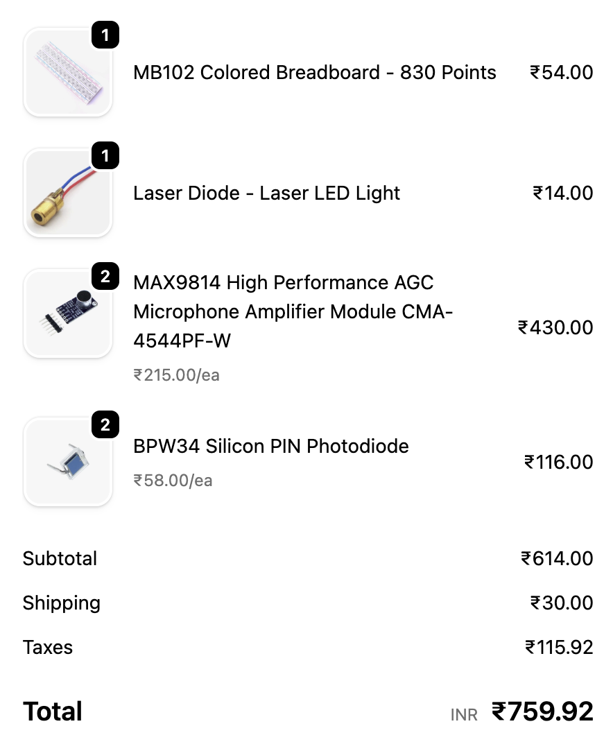
How I Built an Audio Transmitter Using a Laser
To build an audio transmitter using a laser, you must purchase these components from your favourite store: a laser diode, a MAX9814 High Performance AGC Microphone Amplifier Module CMA-4544PF-W, a BPW34 Silicon PIN Photodiode, an IRFZ44N MOSFET, a 1kΩ resistor, and a 470µf 16v capacitor.
Components and Its Use Case
The use case of components to build an audio transmitter is given below.
Laser Diode
A laser diode is used to transmit the data-carrying audio by modulating the laser light through a medium.
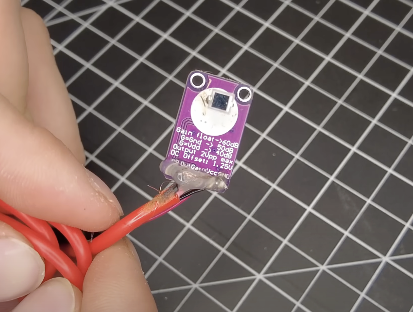
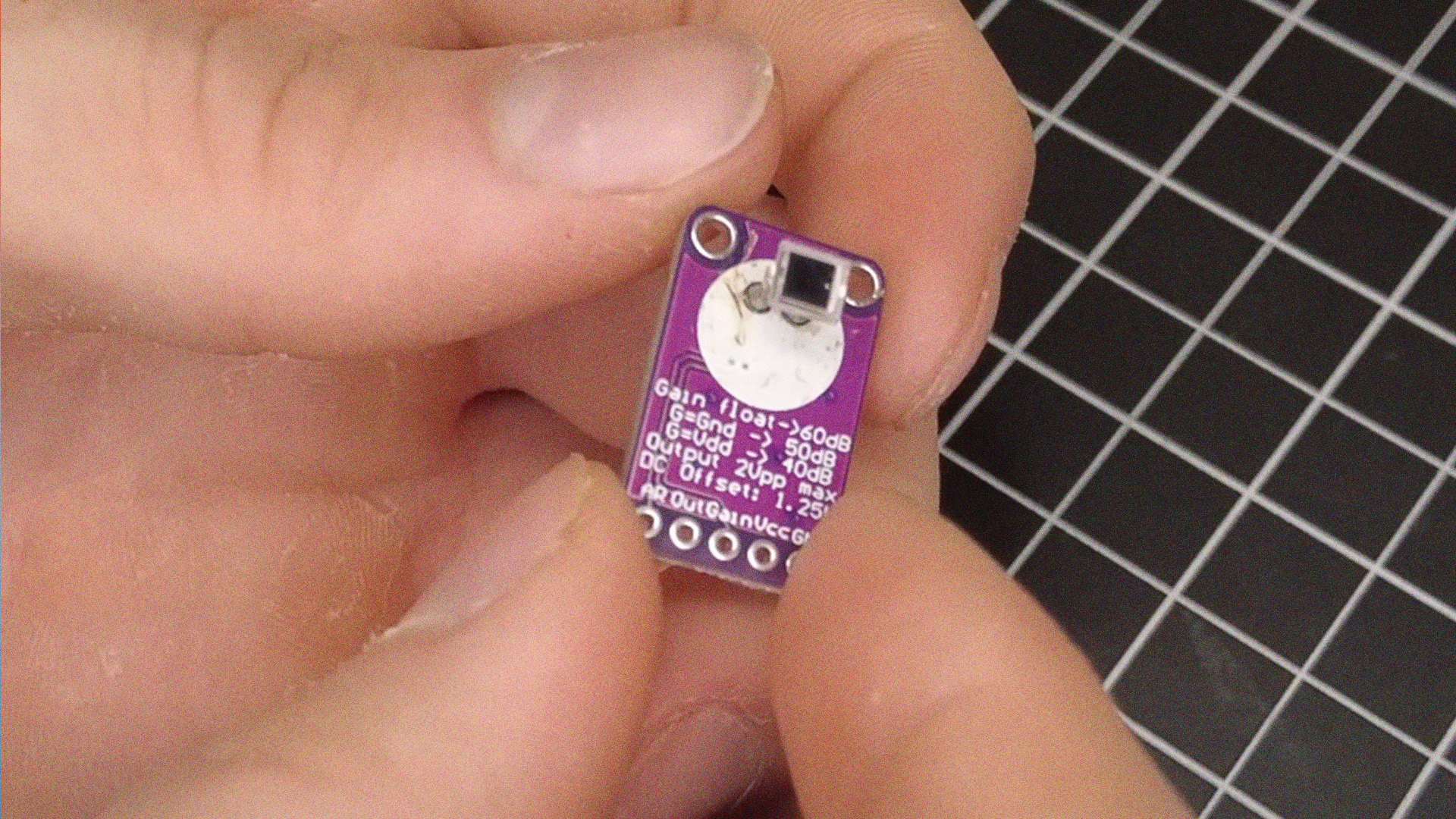
MAX9814 High Performance AGC Microphone Amplifier Module CMA-4544PF-W
This AGC Microphone Amplifier module is used to convert the modulated laser light to electric signals, but the module cannot do it by itself.
BPW34 Silicon PIN Photodiode
It is used as the receiver part where the laser-modulated light converts to electrical pulses, but now you are thinking, “Then why do we need to use a ‘MAX9814 High Performance AGC Microphone Amplifier Module CMA-4544PF-W’?” Hmm, that’s the point. I just mentioned above that the module cannot do the process by itself because it is an audio-to-electric signal converter.
IRFZ44N MOSFET
The IRLZ44N MOSFET is the central part of this circuit and works as a light modulator. The audio signal coming from the jack is applied to its gate, and this controls the flow of current between the drain and source where the laser diode is connected. As the audio waveform varies, the MOSFET changes how much current flows through the laser diode, which causes the laser’s brightness to fluctuate in sync with the sound. In this way, the MOSFET translates the electrical audio signal into an optical signal carried by the laser beam.
1kΩ Resistor
The 1 kΩ resistor is connected in series with the MOSFET’s gate and serves an important protective role. Since the gate of a MOSFET is highly sensitive and requires only a very small charge to switch, the resistor prevents sudden surges of current from the audio source from damaging it. It also helps to stabilise the circuit by reducing noise or oscillations that might otherwise occur if the gate were driven directly. Essentially, this resistor makes sure the audio signal is safely and smoothly fed into the MOSFET.
470µf 16v Capacitor
The 470 µF, 16 V capacitor is placed at the input of the circuit and functions as a coupling capacitor. Its purpose is to block any DC voltage that could come from the audio device and allow only the alternating current part of the signal, the actual audio waveform, to pass through. Without this capacitor, a DC offset might bias the MOSFET incorrectly or even cause harm to the audio source. By isolating DC while passing AC, the capacitor ensures that only the pure audio variations reach the gate of the MOSFET.
Process of Making
Now you have a laser diode, a MAX9814 High Performance AGC Microphone Amplifier Module CMA-4544PF-W, and BPW34 Silicon PIN Photodiode.
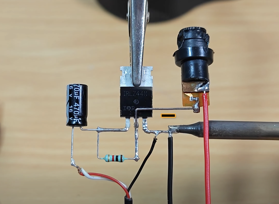
Transmitter
The first step is making the transmitter part. To build the audio transmitter, use these components from the above list: an IRFZ44N MOSFET, a 1 kΩ resistor, a 470 µF 16 V capacitor, and additionally a 3.5 mm audio jack and a DC power source.
Begin with the capacitor, as it will be placed in series with the audio input line. Connect the positive lead of the capacitor to the signal wire coming from the audio jack, while the negative lead will go toward the gate of the MOSFET. This arrangement ensures that only the AC portion of the audio signal passes forward. Next, solder the 1 kΩ resistor from the capacitor’s negative (gate of the MOSFET) terminal to the drain pin of the MOSFET. This resistor limits the current entering the gate and keeps the signal safe and stable. Now, connect the source pin of the MOSFET to the ground line of both the audio input and the power supply. The drain pin of the MOSFET should be wired to the negative terminal of the laser diode. After this, connect the positive terminal of the laser diode to the positive line of the external DC supply.
Plug in the audio jack to a phone or computer, and power the circuit using a small DC supply, usually between 5 V and 12 V depending on your laser module’s rating. When you play music, the audio signal will travel through the capacitor and resistor into the MOSFET’s gate, modulating the brightness of the laser beam in perfect sync with the sound. To complete the setup, you would need a simple receiver circuit with a photodiode and amplifier.
Reciever
To make the receiver, just desolder the microphone from the MAX9814 High Performance AGC Microphone Amplifier Module CMA-4544PF-W. Next, solder the BPW34 silicon PIN photodiode to the place where the microphone was desoldered. Connections of MAX9814 High Performance AGC Microphone Amplifier Module CMA-4544PF-W “Mono aux cable: Red to Out, Black to Ground (GND); Power cable: Red to VCC, Black to GND.” Next, use an amplifier to increase audio quality. Connect the amplifier's input to the Out and GND wires just mentioned above, then power up the circuit through the VCC (+v) and GND (-v). Remember to use different power supplies for these different circuits.